CR-NX Models

Three structures.
A robot for your process.

From injection molding machine unloading to palletizing. Compare the structures and explore the details of robots developed by Carioli Engenharia.

Explore each model

See the structure.
Explore the details.

Overall views and construction details of Carioli designs. Select an image to enlarge it.

Injection molding machine unloading

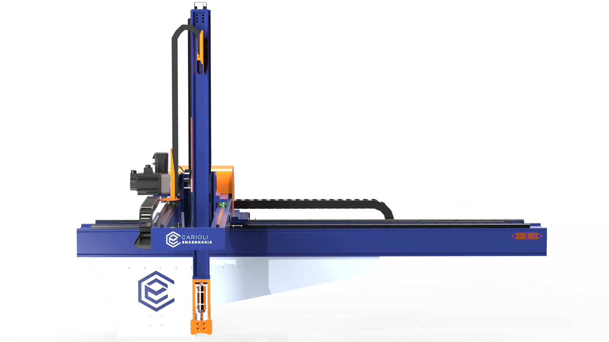
CR-NX-1C

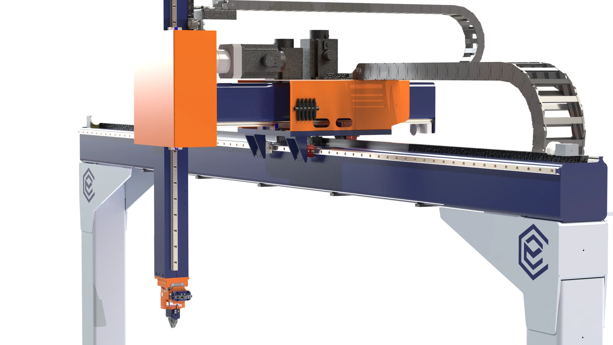
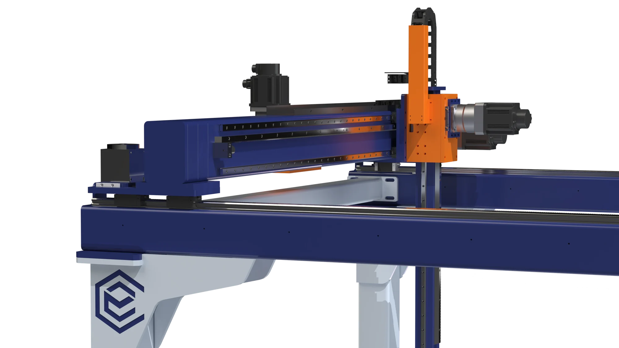
A single-column model, used primarily for unloading products from injection molding machines.
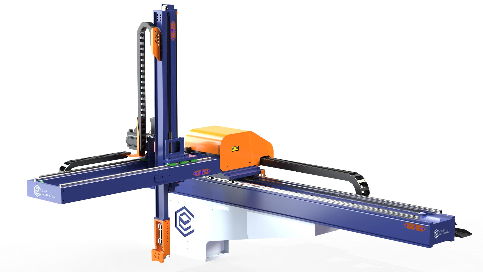
  • Side access to the machine
  • Telescopic Z axis

The single-column structure and cantilevered axis provide a basis for assessing access to the pickup point. A telescopic Z axis is an option for fitting the vertical travel within the available space.

What to assess in your process
  • Part geometry and gripping conditions.
  • Pickup point and destination after removal.
  • Synchronization with the injection molding machine cycle.

Load, axis travel, cycle time and end effector are specified together for the application.

Discuss your application View dimensions and specifications

Technical details

Dimensions and specifications CR-NX-1C
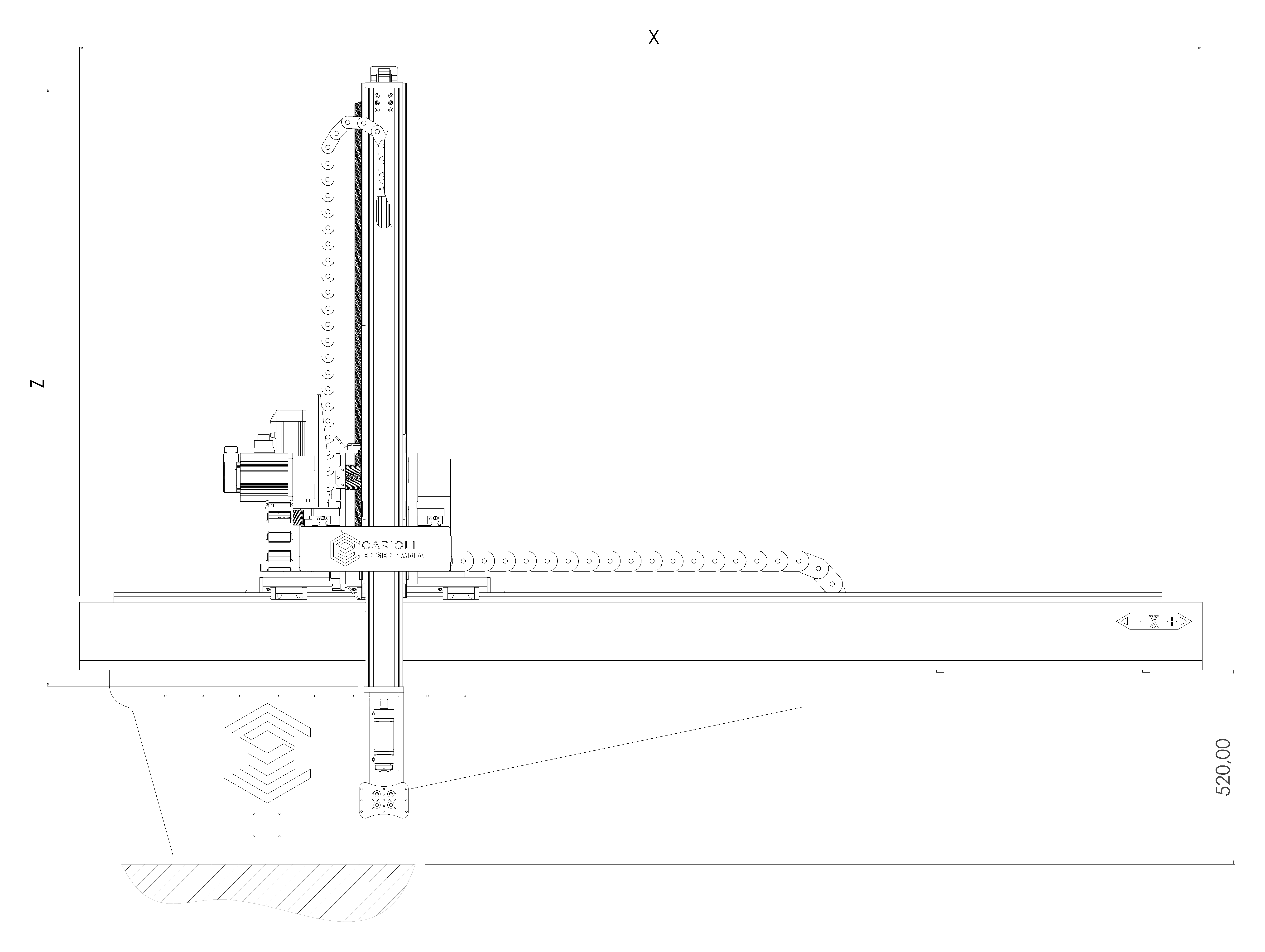
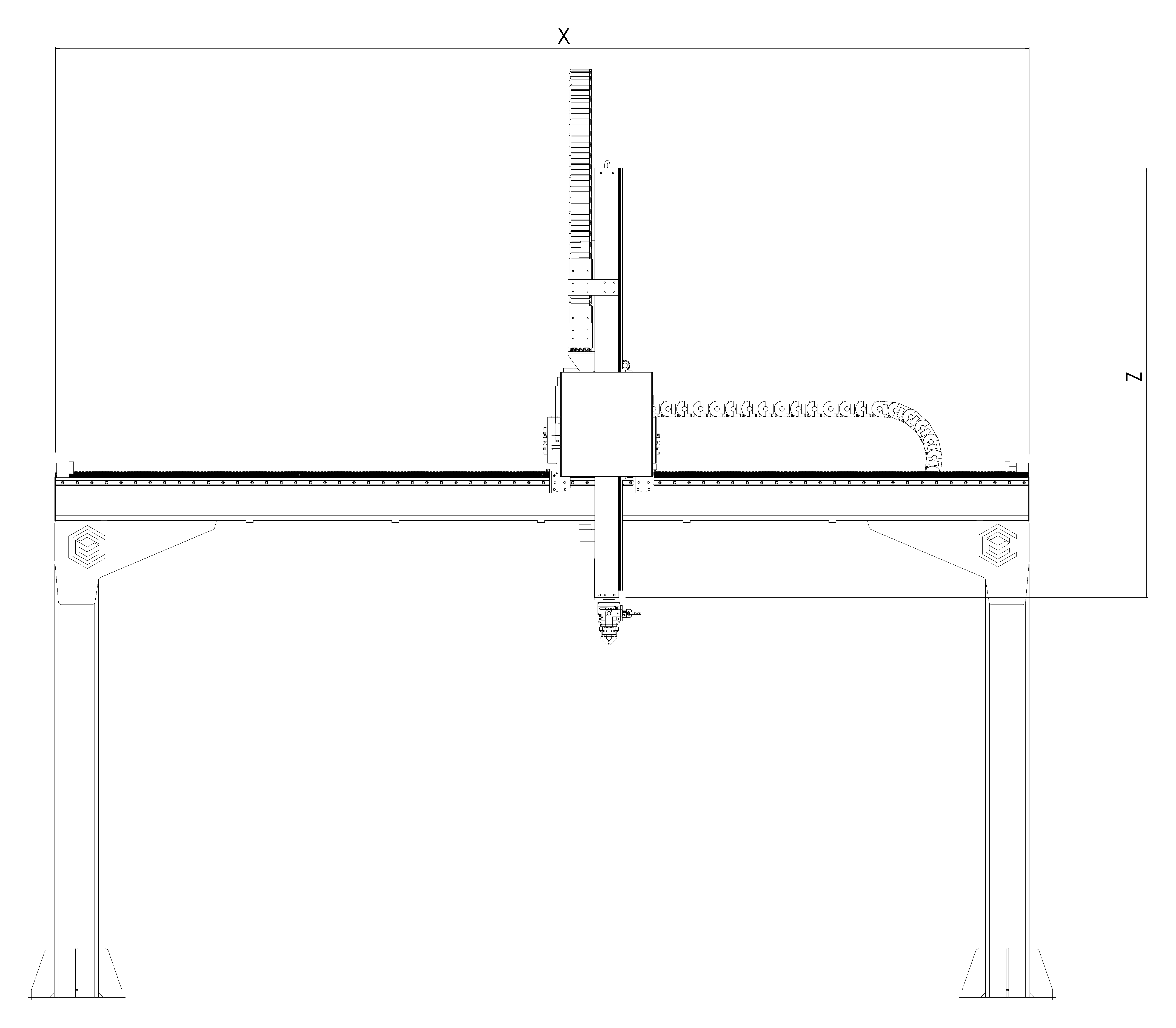
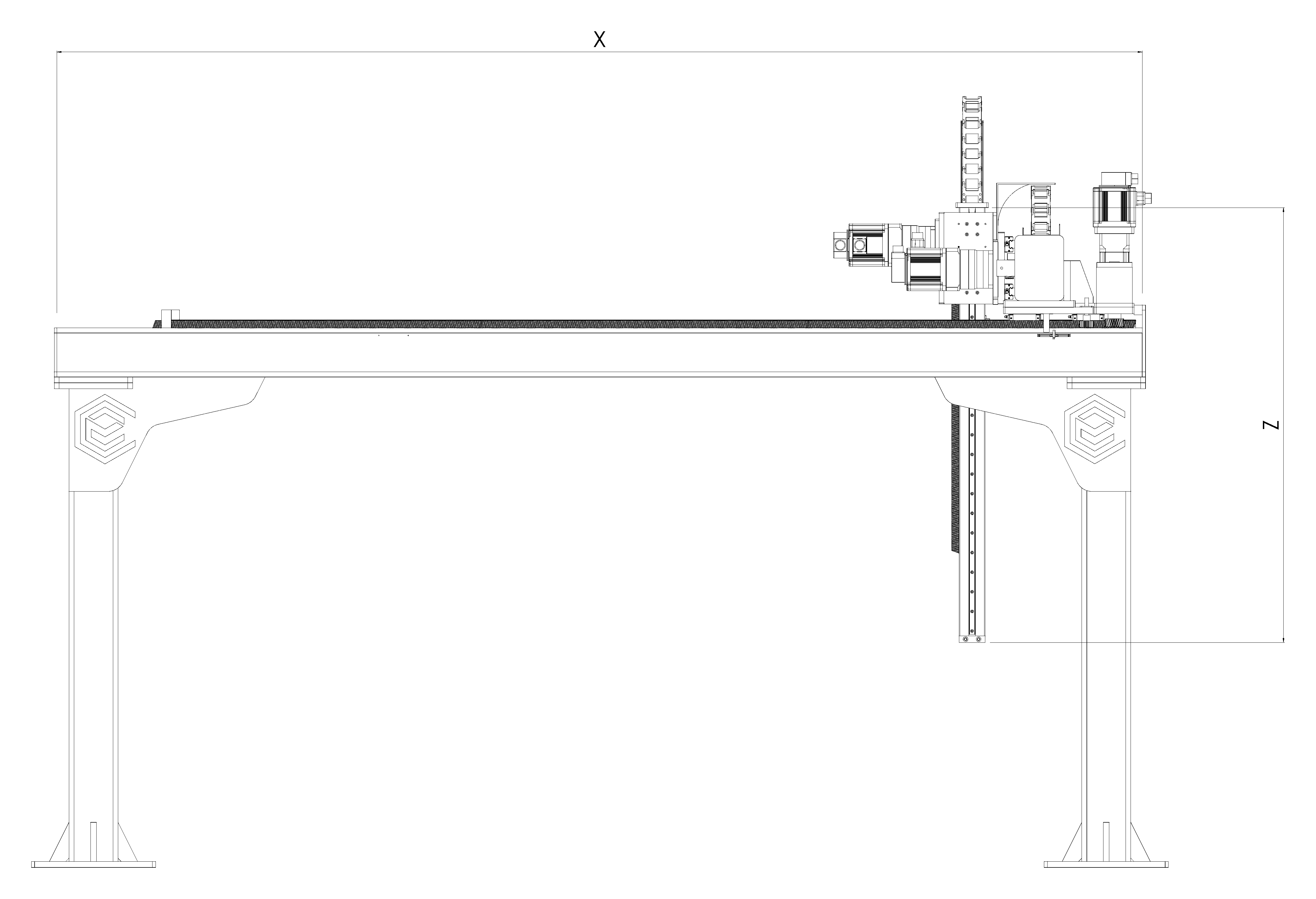
Technical drawing of the Carioli Engenharia CR-NX-1C Cartesian robot in front view, with variable X and Z dimensions.
Front viewX / Z
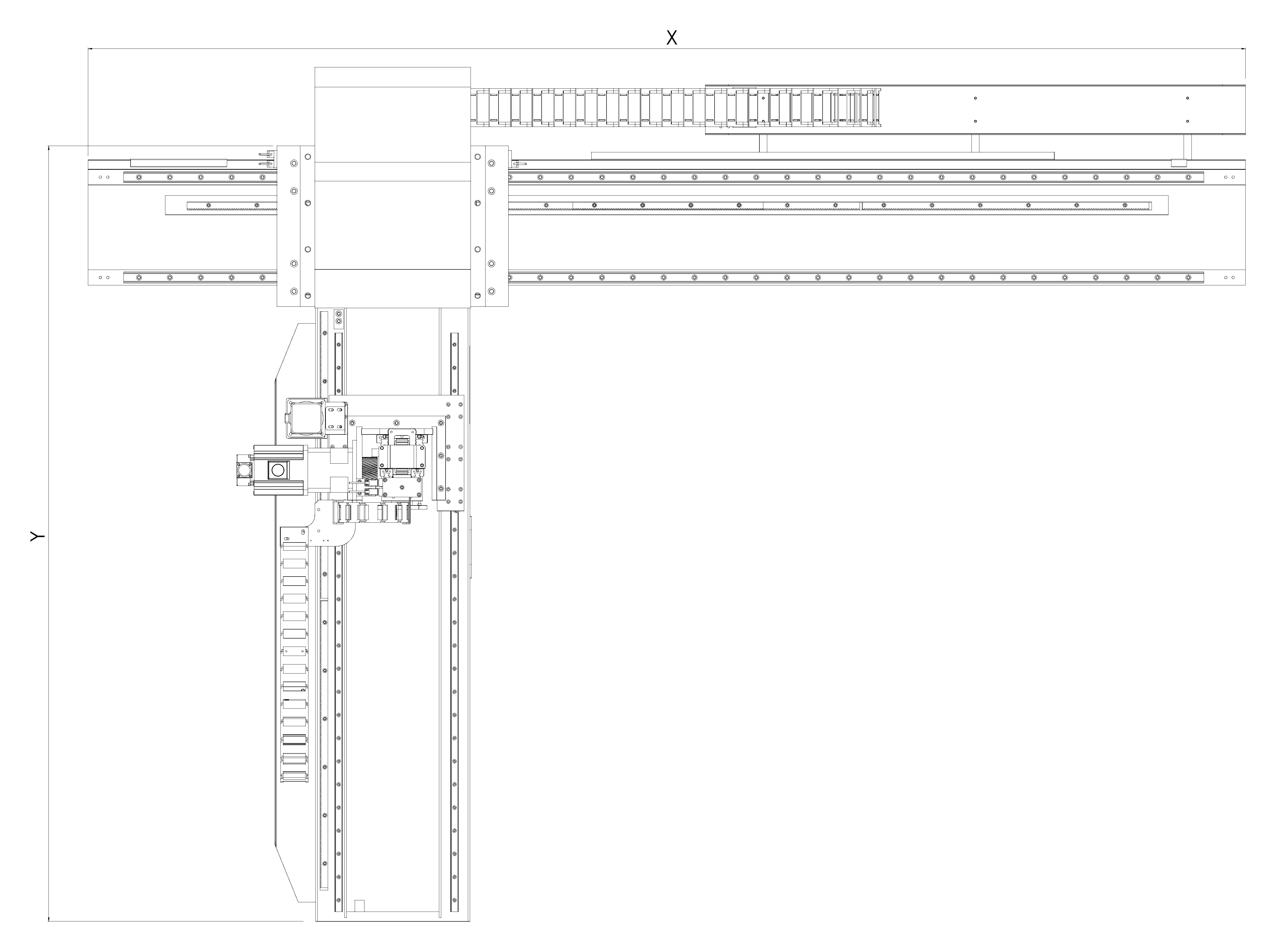
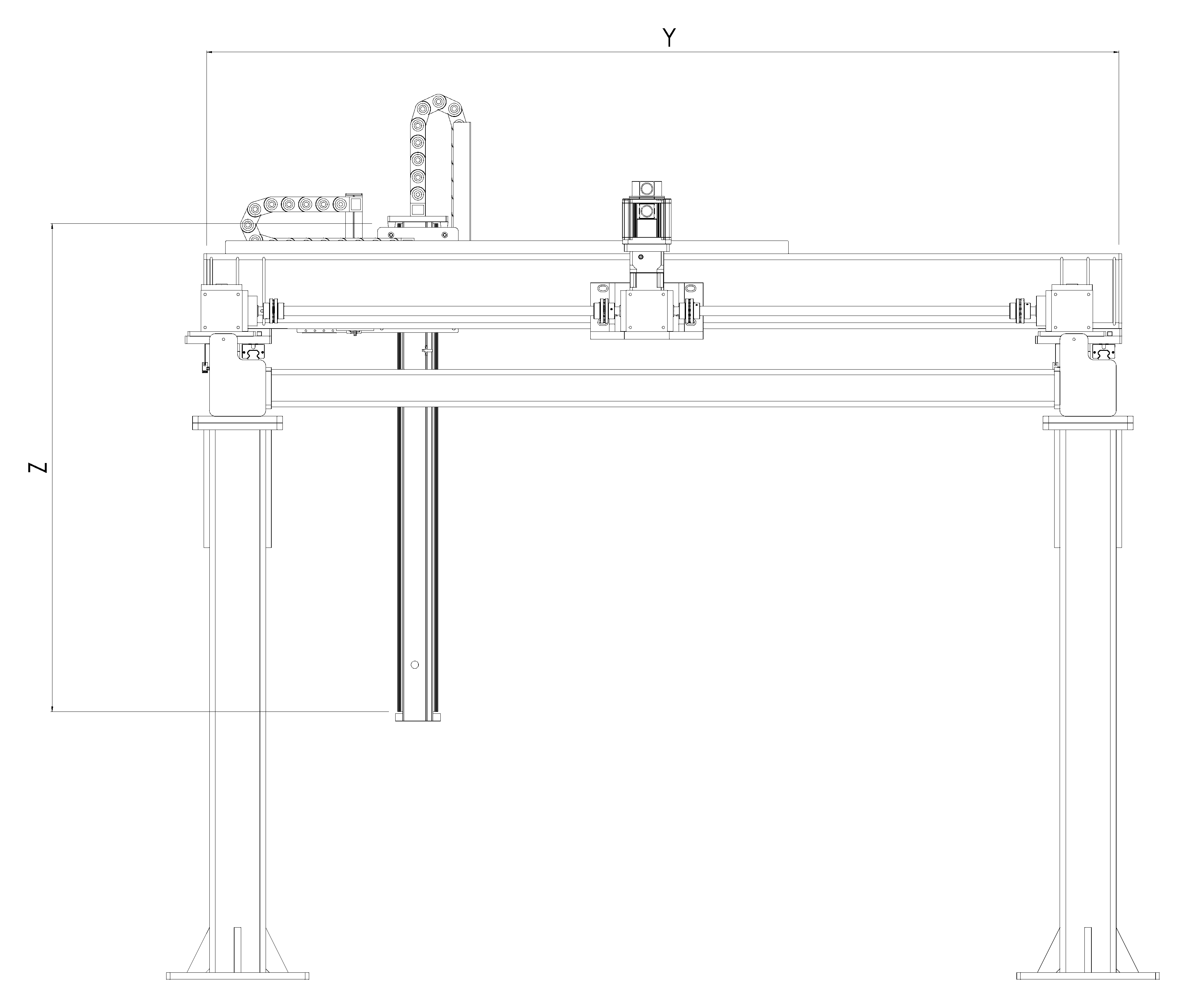
Technical drawing of the Carioli Engenharia CR-NX-1C Cartesian robot in top view, with variable X and Y dimensions.
Top viewX / Y

Reference views from Carioli drawings. X, Y and Z indicate variable design dimensions. See the table for usable travel and overall lengths.

Select a view to enlarge the details.

Proposed preliminary sizing ranges, subject to validation of the complete assembly. Maximum load, travel and speed depend on the configuration and are not necessarily achievable simultaneously.

CR-NX-1C technical specifications
ParameterMin.Max.
Loads
Product loadkg-15
Tool and accessory masskg-5
Total load at the interfacekg-20
Usable travel and overall axis lengths
Usable X travelmm5001,500
Overall X axis lengthmm1,1002,100
Usable Y travelmm300800
Overall Y axis lengthmm1,0001,500
Usable telescopic Z travel — referencemm3001,200
Overall Z axis length — referencemm5501,450
Extended telescopic Z axis — optional
Overall Z axis lengthmm-4,000
Expected usable Z travel in the 4,000 mm versionmm3,3003,350
Helical rack and pinion — maximum-load scenario
X / Y / Z servo motorsW750 / 400 / 400
X / Y / Z motor-to-pinion reduction ratio5:1 / 5:1 / 25:1
Rated servo motor speedrpm3,000
X speedm/s0.001.00
Y speedm/s0.001.00
Z speedm/s0.000.40
X accelerationm/s²0.001.50
Y accelerationm/s²0.001.50
Z accelerationm/s²0.000.50
Alternative drives — specific travel and speed ranges
X ball screwUsable travel: 500 to 1,000 mm; speed: 0 to 0.31 m/s.
Y ball screwUsable travel: 300 to 800 mm; speed: 0 to 0.44 m/s.
Non-telescopic Z ball screwUsable travel: 300 to 800 mm; speed: 0 to 0.22 m/s.
X / Y timing beltUsable X / Y travel: 500–1,500 / 300–800 mm; speed: 0 to 1.00 m/s.

The total load at the interface includes the product, tool and accessories. Overall lengths refer to the axes; they do not represent the installation height. “-” indicates an unspecified minimum.

Configuration conditions
Ball screws
direct 1:1 drive, fixed–supported end arrangement and acceleration up to 0.50 m/s²; X / Y / Z motors rated at 750 / 400 / 400 W. The Z ball screw applies to the non-telescopic version.
Timing belts
motors from the horizontal-axis scenario, with X / Y reduction ratios of 5:1 / 5:1. Belt profile, width and tensile cord depend on the selected assembly.
Rack-driven Z axis
400 W and a 25:1 reduction ratio; speed of 0.40 m/s with acceleration up to 0.50 m/s². The calculation assumes a 2:1 telescopic ratio; effective masses, the ratio between stages and safe axis retention must be verified.
Extended telescopic Z axis
rack-and-belt option available for the 1C and 1P. It requires dedicated sizing; the reference loads and speeds do not automatically apply to the 4,000 mm option.
Component references: DeltaHIWIN

Pick & place

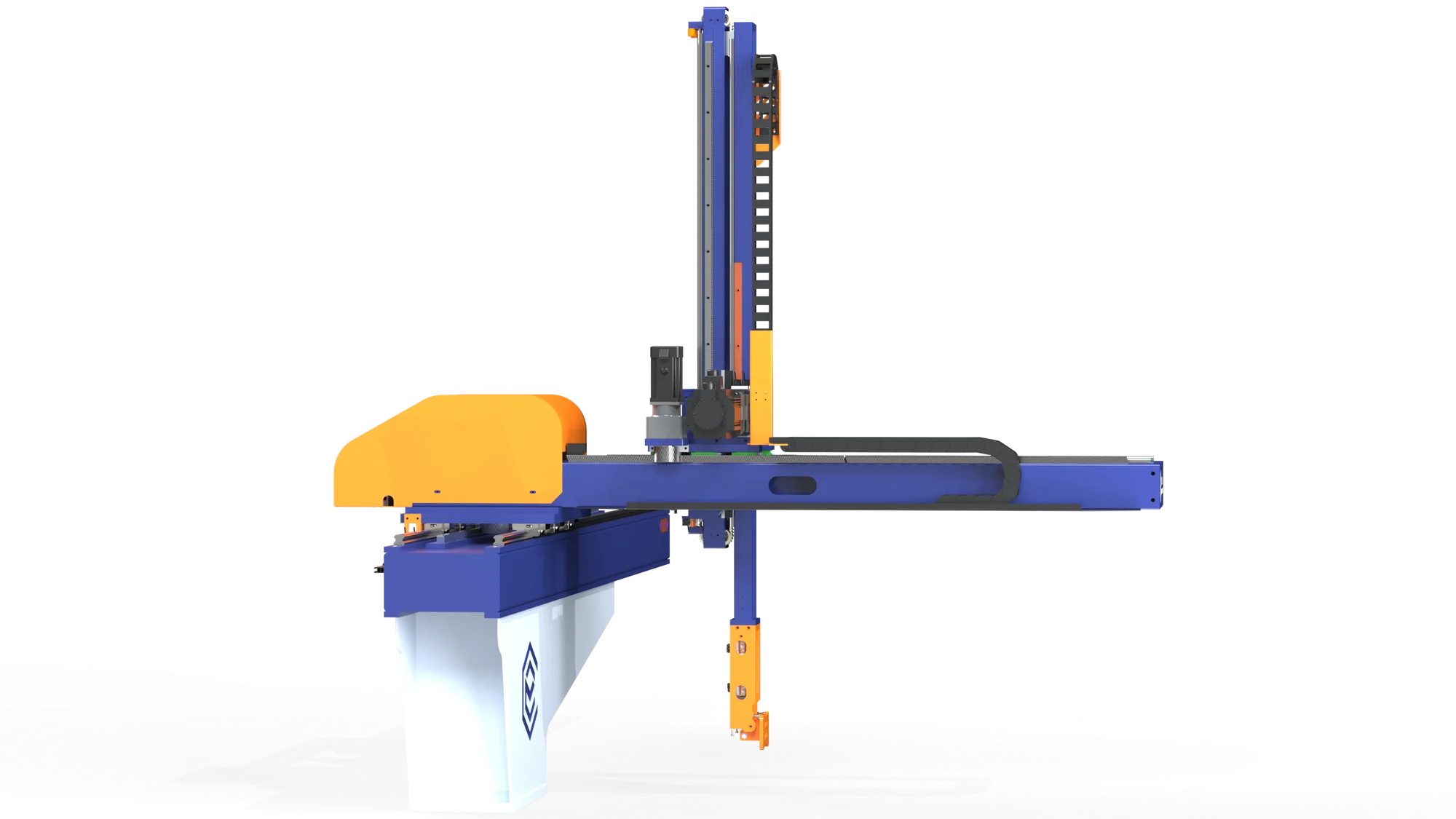
CR-NX-1P

A single-gantry model, used primarily to pick, transfer and position products.

  • Transfer between stations
  • Telescopic Z axis option

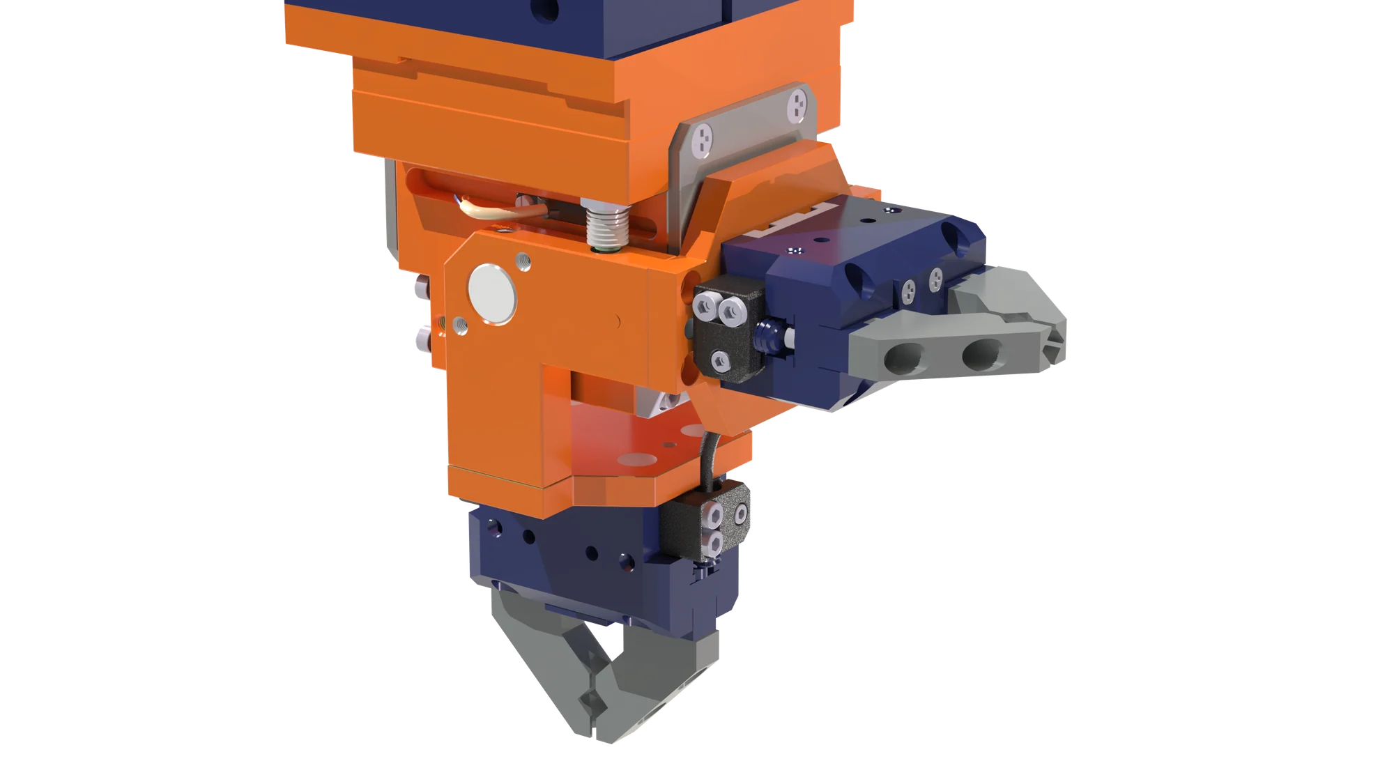
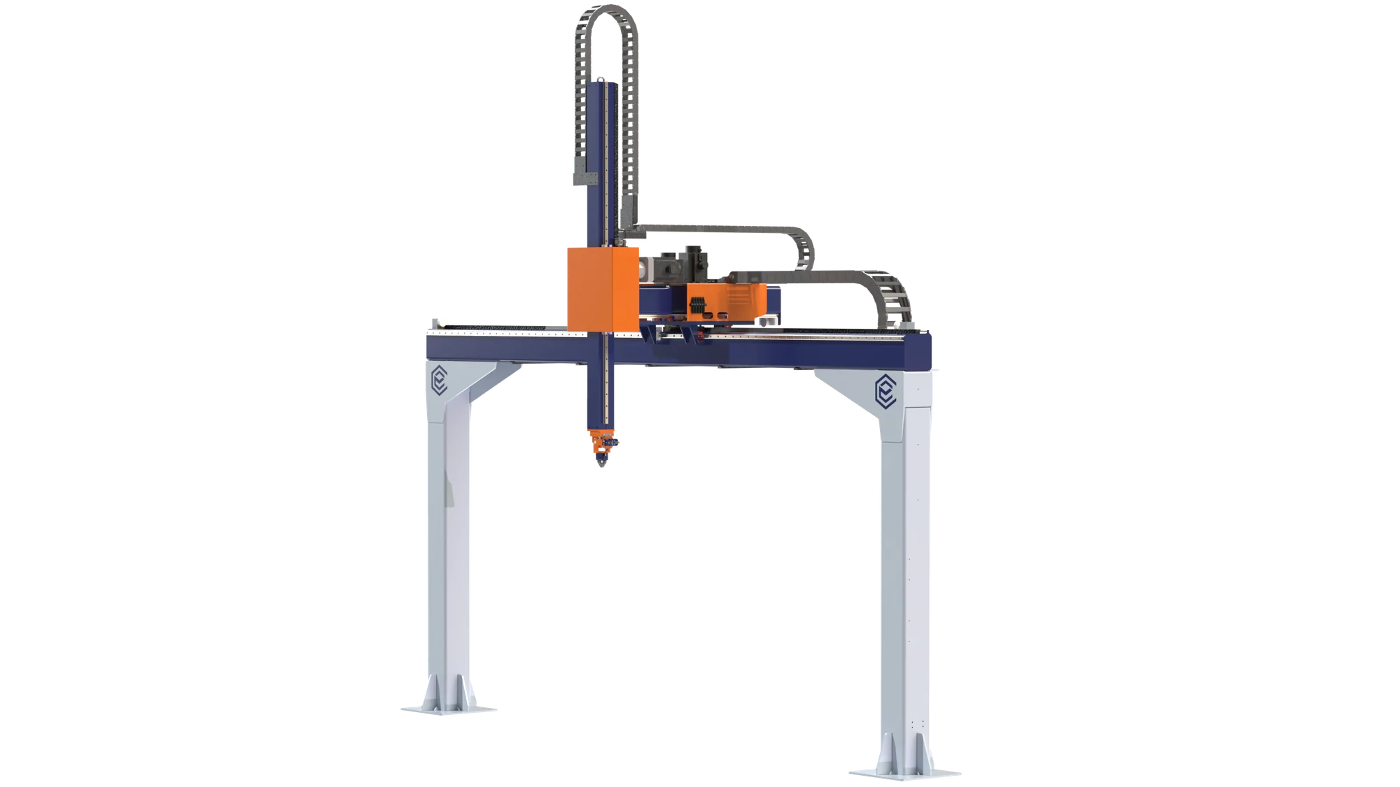
The gantry supports the motion assembly, with a cantilevered Y axis. The gripping tool is configured to suit the product and operation. A telescopic Z axis is also available as a configuration option.

What to assess in your process
  • Product pickup and placement positions.
  • Load trajectory, orientation and stability.
  • Production rate and integration with the stations.

Load, axis travel, cycle time and end effector are specified together for the application.

Discuss your application View dimensions and specifications

Technical details

Dimensions and specifications CR-NX-1P

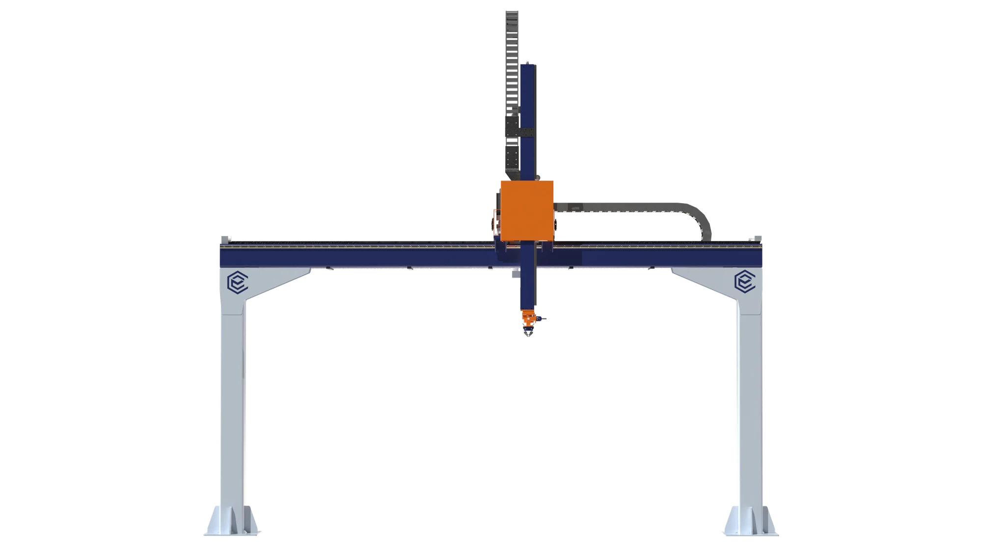
Technical drawing of the Carioli Engenharia CR-NX-1P Cartesian robot in front view, with variable X and Z dimensions.
Front viewX / Z
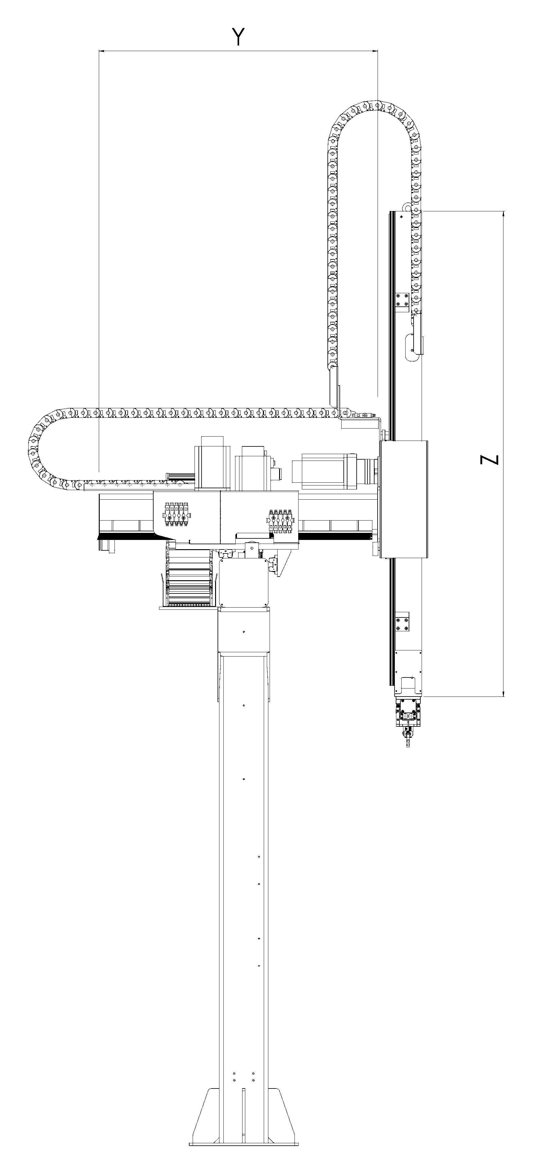
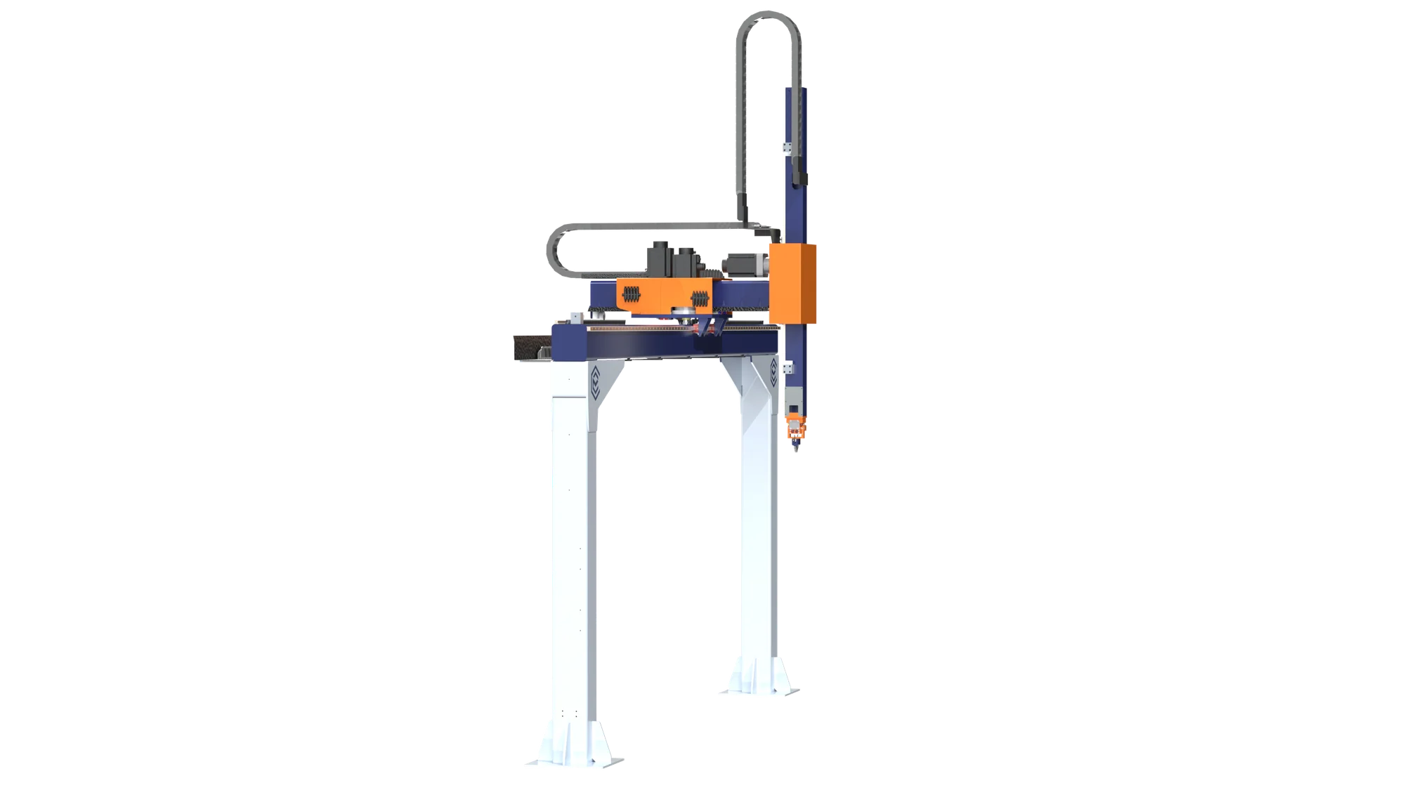
Technical drawing of the Carioli Engenharia CR-NX-1P Cartesian robot in side view, with variable Y and Z dimensions.
Side viewY / Z

Reference views from Carioli drawings. X, Y and Z indicate variable design dimensions. See the table for usable travel and overall lengths.

Select a view to enlarge the details.

Proposed preliminary sizing ranges, subject to validation of the complete assembly. Maximum load, travel and speed depend on the configuration and are not necessarily achievable simultaneously.

CR-NX-1P technical specifications
ParameterMin.Max.
Loads
Product loadkg-40
Tool and accessory masskg-10
Total load at the interfacekg-50
Usable travel and overall axis lengths
Usable X travelmm8003,000
Overall X axis lengthmm1,3003,500
Usable Y travelmm4001,200
Overall Y axis lengthmm9501,750
Usable non-telescopic Z travel — referencemm4001,500
Overall Z axis length — referencemm1,0502,150
Extended telescopic Z axis — optional
Overall Z axis lengthmm-4,000
Expected usable Z travel in the 4,000 mm versionmm3,3003,350
Helical rack and pinion — maximum-load scenario
X / Y / Z servo motorsW750 / 750 / 1,000
X / Y / Z motor-to-pinion reduction ratio10:1 / 5:1 / 10:1
Rated servo motor speedrpm3,000
X speedm/s0.000.80
Y speedm/s0.001.00
Z speedm/s0.000.50
X accelerationm/s²0.001.50
Y accelerationm/s²0.001.50
Z accelerationm/s²0.000.80
Alternative drives — specific travel and speed ranges
X ball screwUsable travel: 800 to 1,500 mm; speed: 0 to 0.40 m/s.
Y ball screwUsable travel: 400 to 1,000 mm; speed: 0 to 0.34 m/s.
Z ball screwUsable travel: 400 to 1,200 mm; speed: 0 to 0.29 m/s.
X / Y timing beltUsable X / Y travel: 800–3,000 / 400–1,200 mm; speed: 0–0.80 / 0–1.00 m/s.

The total load at the interface includes the product, tool and accessories. Overall lengths refer to the axes; they do not represent the installation height. “-” indicates an unspecified minimum.

Configuration conditions
Ball screws
direct 1:1 drive, fixed–supported end arrangement and acceleration up to 0.50 m/s²; X / Y / Z motors rated at 750 / 750 / 1,000 W. The Z ball screw applies to the non-telescopic version.
Timing belts
motors from the horizontal-axis scenario, with X / Y reduction ratios of 10:1 / 5:1. Belt profile, width and tensile cord depend on the selected assembly.
Rack-driven Z axis
1,000 W in the reference non-telescopic configuration; verify effective masses, thermal conditions and the gearbox, as the additional torque margin is limited.
Extended telescopic Z axis
rack-and-belt option available for the 1C and 1P. It requires dedicated sizing; the reference loads and speeds do not automatically apply to the 4,000 mm option.
Component references: DeltaHIWIN

Palletizing

CR-NX-2P

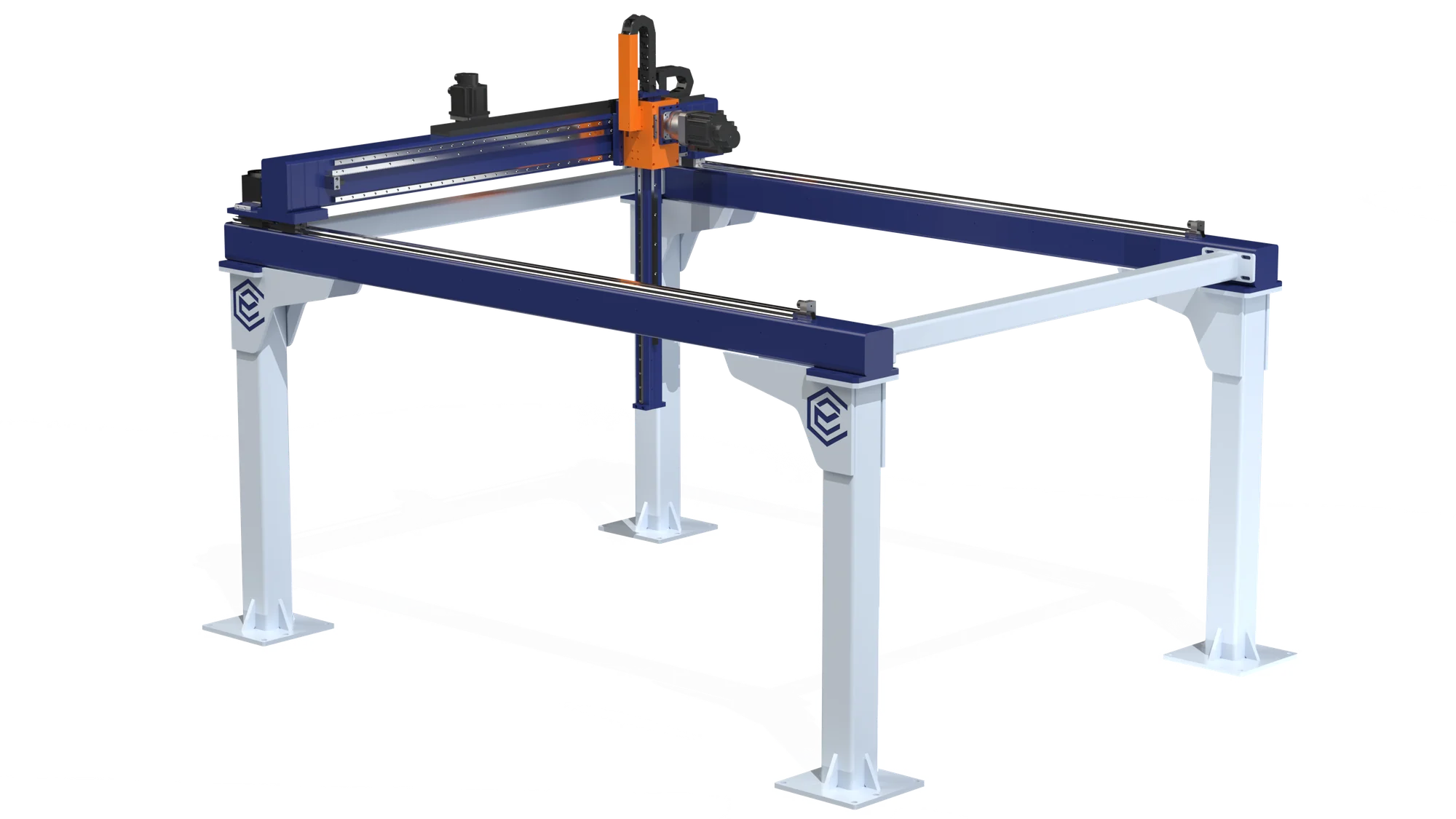
A two-gantry model for palletizing, with X, Y and Z motion and gripper rotation in the reference configuration. The Carioli system calculates layers and positions from the product dimensions.

  • Work area between gantries
  • Synchronization of both sides

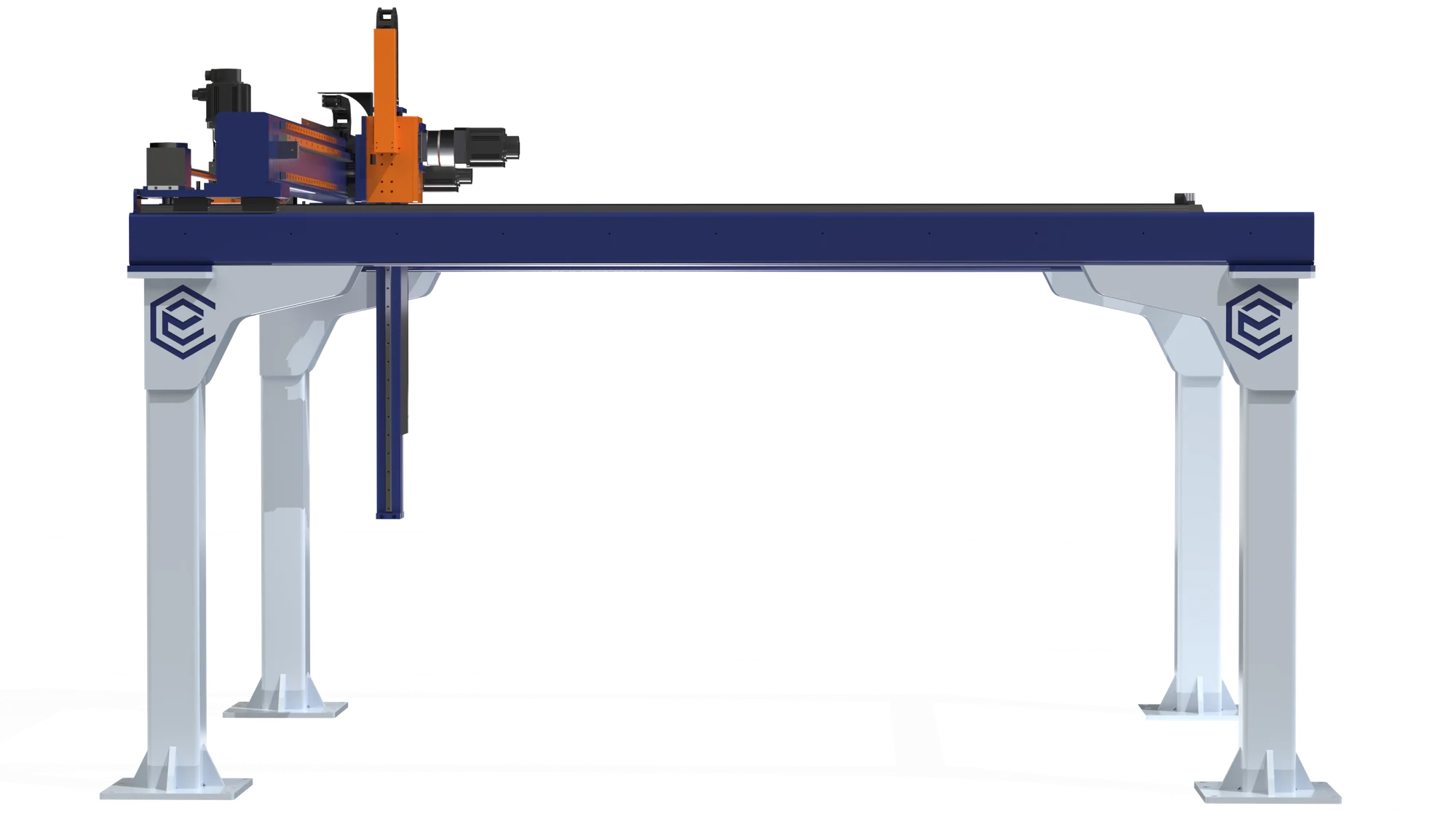
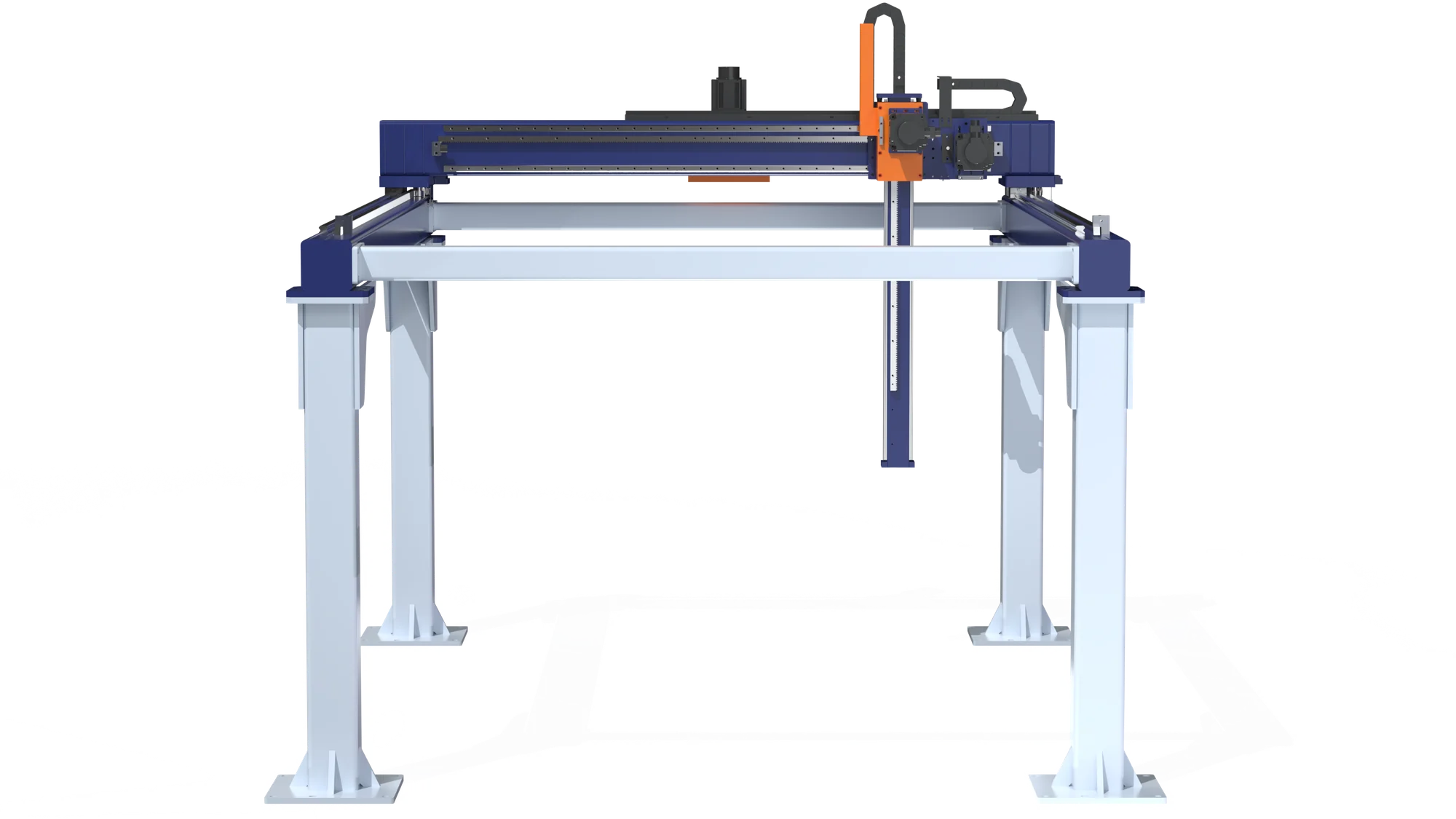
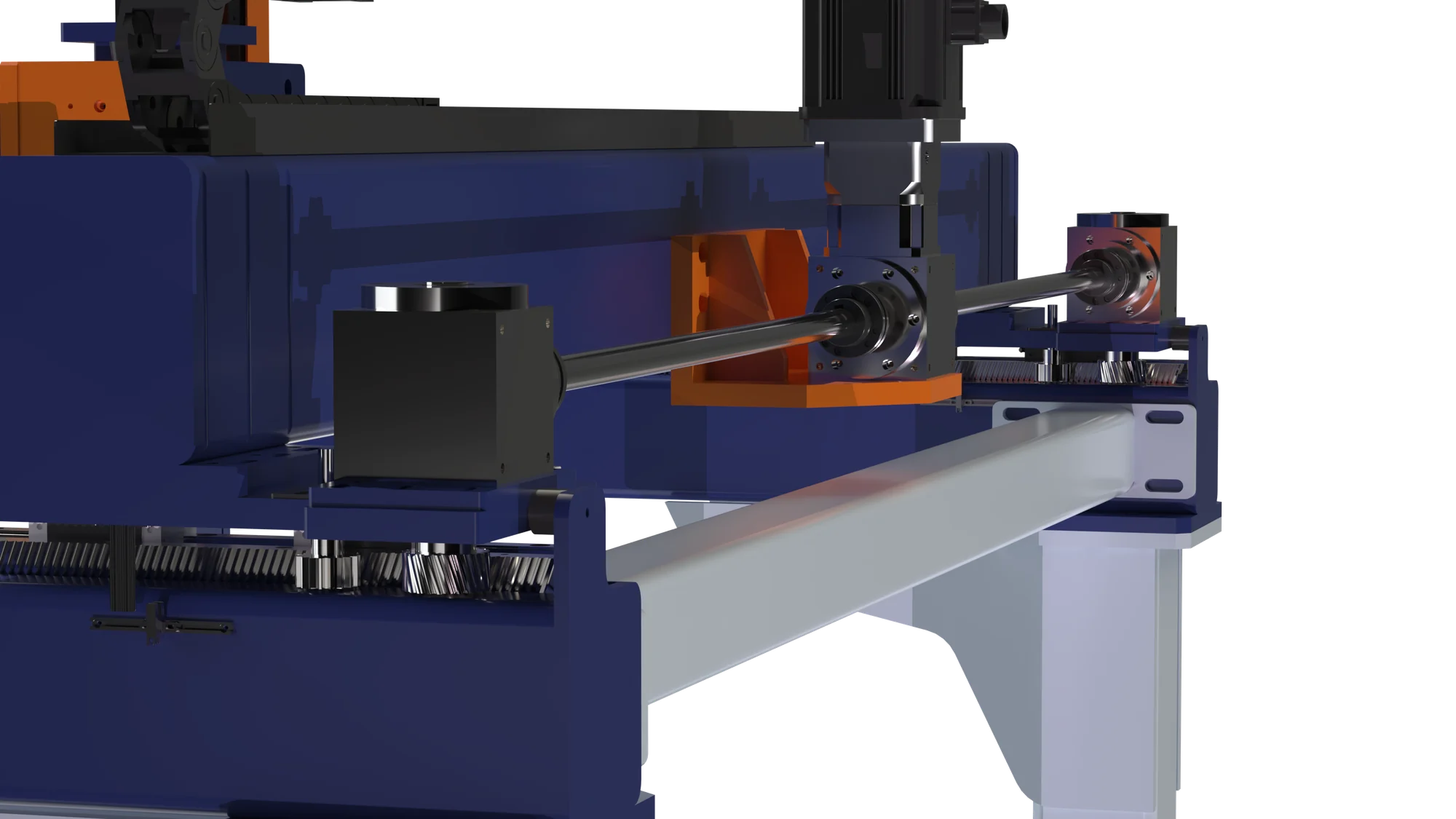
The crossbeam travels along both sides of the structure. Depending on the design, synchronization can use a single servo motor and a mechanical cross-shaft, as shown in the rendering, or two electronically synchronized servo motors.

What to assess in your process
  • Dimensions and mass of the products and pallets.
  • Layer patterns and stacking height.
  • Product infeed and pallet changeover.

Load, axis travel, cycle time and end effector are specified together for the application.

Discuss your application View dimensions and specifications

Technical details

Dimensions and specifications CR-NX-2P

Technical drawing of the Carioli Engenharia CR-NX-2P Cartesian robot in front view, with variable X and Z dimensions.
Front viewX / Z
Technical drawing of the Carioli Engenharia CR-NX-2P Cartesian robot in side view, with variable Y and Z dimensions.
Side viewY / Z

Reference views from Carioli drawings. X, Y and Z indicate variable design dimensions. See the table for usable travel and overall lengths.

Select a view to enlarge the details.

Proposed preliminary sizing ranges, subject to validation of the complete assembly. Maximum load, travel and speed depend on the configuration and are not necessarily achievable simultaneously.

CR-NX-2P technical specifications
ParameterMin.Max.
Loads
Product loadkg-1,000
Tool and accessory masskg-150
Total load at the interfacekg-1,150
Usable travel and overall axis lengths
Usable X travel with helical rack and pinionmm1,50020,000
Overall X axis lengthmm2,24020,740
Usable Y travelmm8003,000
Overall Y axis lengthmm1,5953,795
Usable non-telescopic Z travelmm5002,000
Overall Z axis lengthmm8102,310
Helical rack and pinion — maximum-load scenario
X / Y / Z servo motorsW2,000 / 2,000 / 2,000
X / Y / Z motor-to-pinion reduction ratio20:1 / 15:1 / 100:1
Rated servo motor speedrpm2,000
X speedm/s0.000.60
Y speedm/s0.000.50
Z speedm/s0.000.08
X accelerationm/s²0.000.30
Y accelerationm/s²0.000.30
Z accelerationm/s²0.000.10
2P model configuration
X / Y / Z drive mechanismHelical rack and pinion
Synchronization of both sides of XOne servo motor with a mechanical cross-shaft; alternative: two electronically synchronized servo motors.
Reference servo motor for the maximum-load scenario2 kW · 2,000 rpm · 9.55 N·m

The total load at the interface includes the product, tool and accessories. Overall lengths refer to the axes; they do not represent the installation height. “-” indicates an unspecified minimum.

Configuration conditions
Power rating
2 kW per axis applies to the 1,000 kg product-load scenario. Power ratings for other configurations are determined by the application; this is not a mandatory rating across the entire 2P range.
Drive
the 2 kW variant rated at 3,000 rpm is not equivalent to the 2,000 rpm reference. Verify gearboxes, efficiency, inertias and thermal conditions.
Rack-driven Z axis
the 100:1 reduction ratio yields the proposed speed of up to 0.08 m/s. The additional torque margin is limited; effective masses, gearbox capacity and safe retention of the axis and load must be verified.
Structure and installation
usable X travel of up to 20 m requires supports and alignment according to the installation design; verify crossbeam stiffness, moments applied by the tool and synchronization of both sides.

Component references: DeltaHIWIN

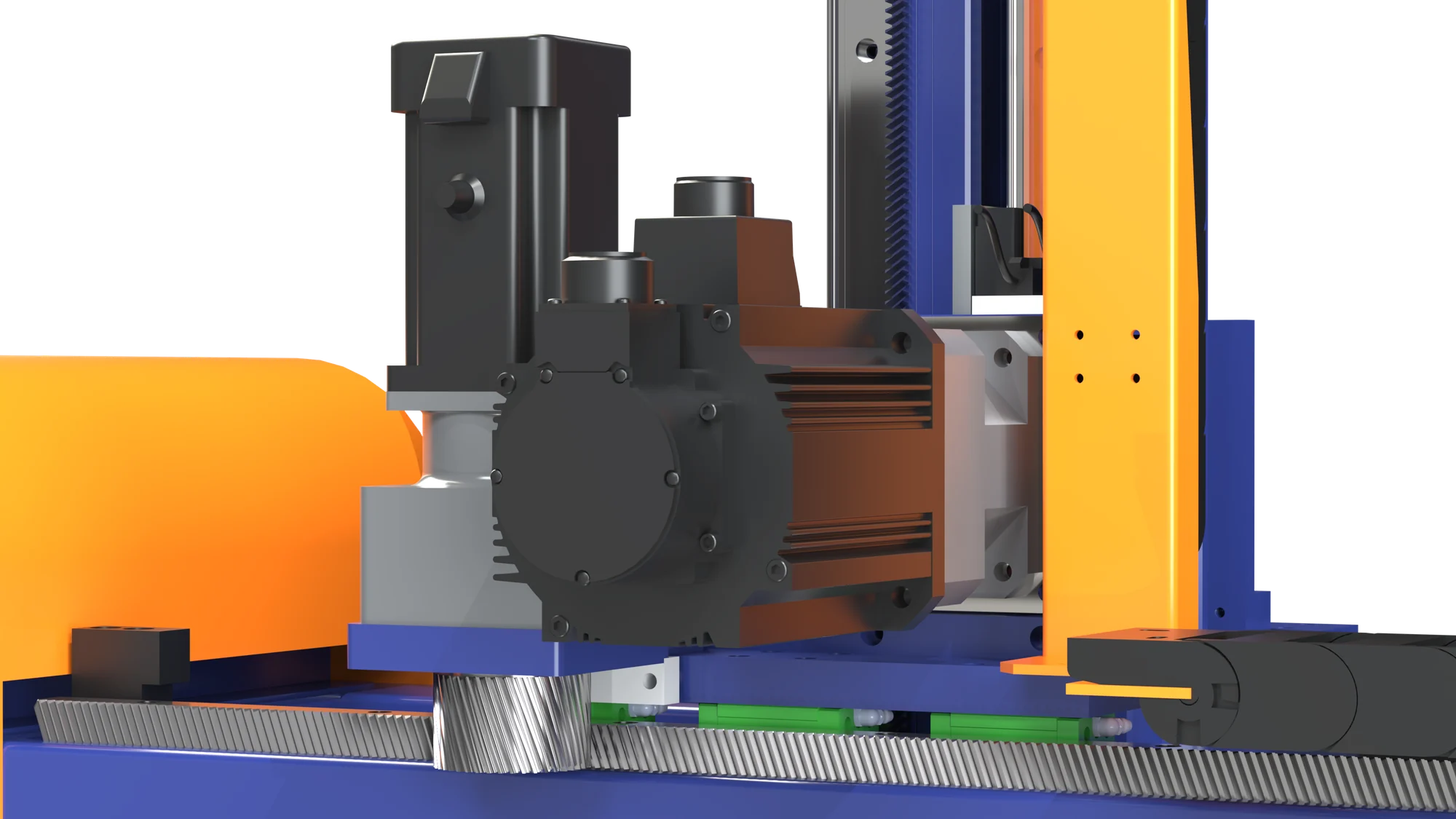
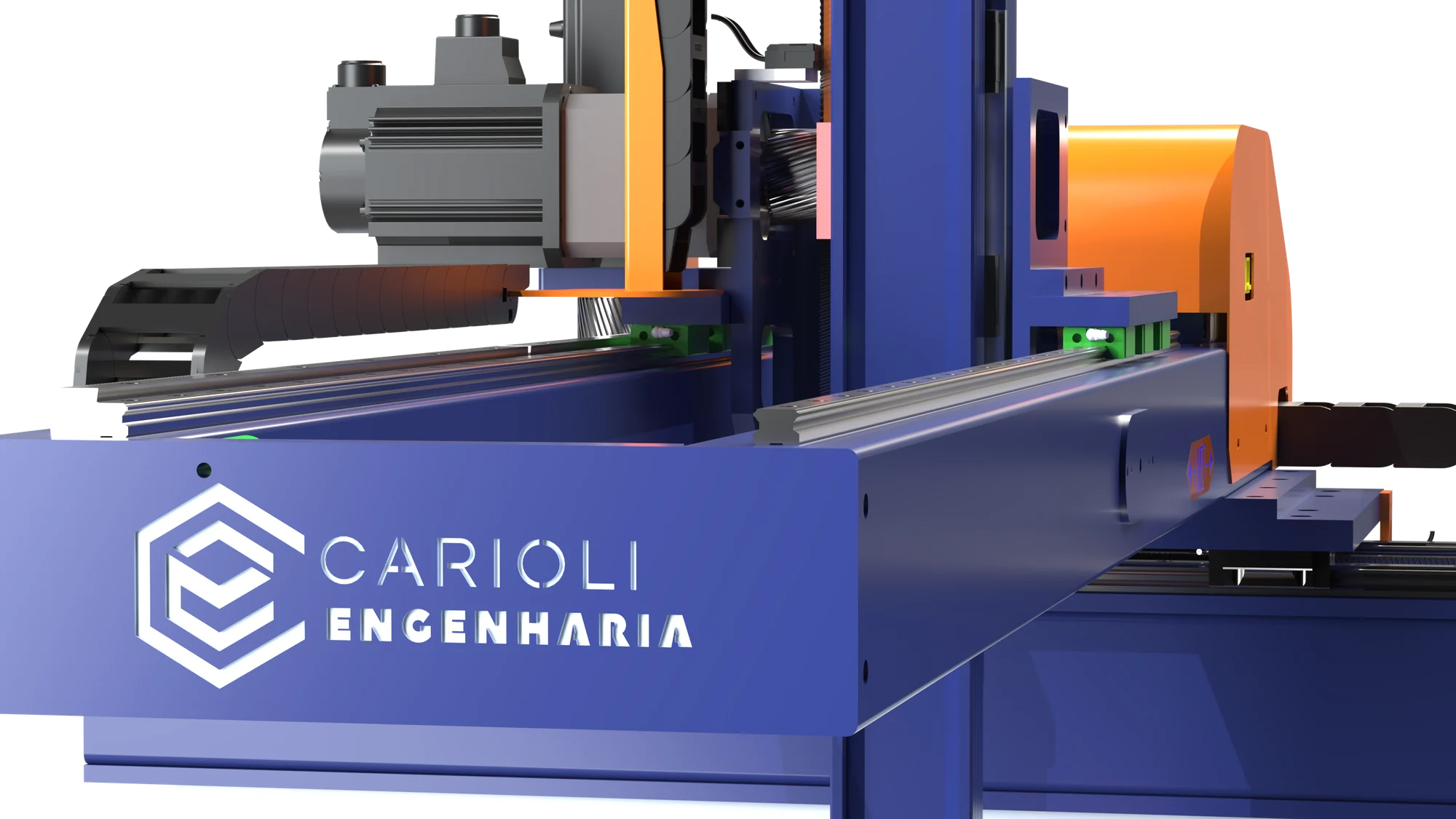
Renderings of Carioli designs. End effectors, guarding and the final configuration depend on the application.

From selection to integration

The model fits the process.

The main applications guide the initial discussion. Selection also considers pickup and placement points, product characteristics, available space and production rate.

The robot can be part of a cell integrated with existing conveyors, fixtures and equipment to meet the needs of the operation.

Explore the robotic cell

Information needed to select the configuration

Product and gripper
Product weight, dimensions and handling conditions, including the gripping tool.
Motion and cycle time
Axis travel, positions, orientation and time available for each step.
Layout and interfaces
Usable area, access and communication with process equipment.
Prepare your application brief

Palletizing with the CR-NX-2P

New products.
The same operating logic.

The Carioli system calculates positions, layers and paths from the product dimensions. In supported configurations, the operator adjusts parameters through the HMI without manually teaching every motion point.

Explore the Carioli system
Load orientation
Gripper rotation allows the product to be oriented and its position alternated within the pallet layers.
Grip position compensation
The mathematical model accounts for the box pickup point when calculating the placement position.
Mechanical configuration by axis
The configuration can combine different transmissions to meet axis travel, load and motion requirements.

Technology and components

Explore the configuration components.

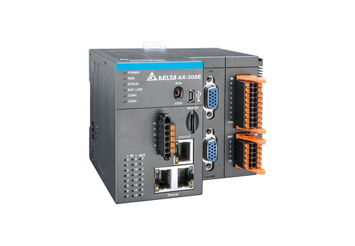
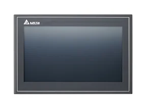
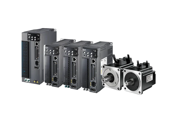
AX-308 controller, ASDA-B3 servo system and DOP-110WS HMI: the Delta platform works with the tooling, transmissions and system developed by Carioli.

The range combines Delta technology with Carioli engineering. Power ratings, axis travel, tooling and enabled features are defined for the application and detailed in the technical proposal.

Delta AX-308E motion controller with connection terminals and communication interfacesDelta AX-308E motion controllerCoordinated movement in EtherCATDelta AX-308 Controller

Motion controller from the AX-3 family, based on CODESYS. Coordinates the CR-NX axes and the exchange of signals with the line's machines.

Schedule
CODESYS, with IEC 61131-3 languages and PLCopen motion functions.
Timing
Up to 8 servo axes via EtherCAT on the controller. The amount used depends on the robot configuration.
Trajectories
Multi-axis interpolation, electronic gearing and electronic cam to coordinate movements.
Integration
OPC UA, EtherNet/IP and Modbus for communication with supervisors and other systems, according to the project interfaces.
Expansion
16 onboard digital inputs and 8 outputs, with expansion via AS series modules.
Delta Documentation · AX-308E
Delta DOP-110WS touchscreen interface, with 10.1-inch widescreen displayDelta DOP-110WS · operation interface10.1-inch screen operationDelta DOP-110WS HMI

The touchscreen interface concentrates commands, parameters and process information. The operator follows the machine and configures the application data on the screen.

Screen
10.1-inch widescreen TFT, 1024 × 600 resolution and integrated Ethernet.
Operation
Recipes, trend graphs and alarm history, depending on the configured screens and functions.
Monitoring
VNC server and browser monitoring of registrars. Access depends on the network and configured permissions.
Remote access
It can be restricted to monitoring, without remote commands, depending on the interface configuration.
Records
Features for sending alarms by email and time synchronization via NTP, when enabled in the project.
Delta Documentation · DOP-110WS
Delta ASDA-B3 family servodrive and servomotorDelta ASDA-B3 · drive and servomotor24-bit position feedbackASDA-B3 Delta Servo System

The drive and servomotor assembly transforms the calculated trajectories into movement. Each axis is dimensioned according to the load, the axis travel and the application cycle.

Encoder
24-bit resolution: 16,777,216 positions per motor revolution. The repeatability of the robot also depends on the mechanics and application.
Tuning
Autotuning and vibration suppression features support adjusting the drive to load dynamics.
Sizing
Power and torque selected for each axis, considering the product, gripper, drive system and path.
Security
Safe Torque Off (STO) integrated into the safety chain, according to the specified drive and system design.
Delta Documentation ASDA-B3
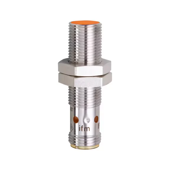
Example of cylindrical inductive sensor with threaded metal body and connectorInductive sensor · reference imageHoming and limit switchesInductive sensors

Non-contact mechanical detection provides position references for the axes and travel limit signals to the controller.

Reference
Axis homing combined with servomotor encoder reading.
Limits
Limit switch signals and software travel limits help control the motion envelope.
Selection
Model, range and environmental protection defined for assembly and operating conditions.
Reference image · ifm electronic
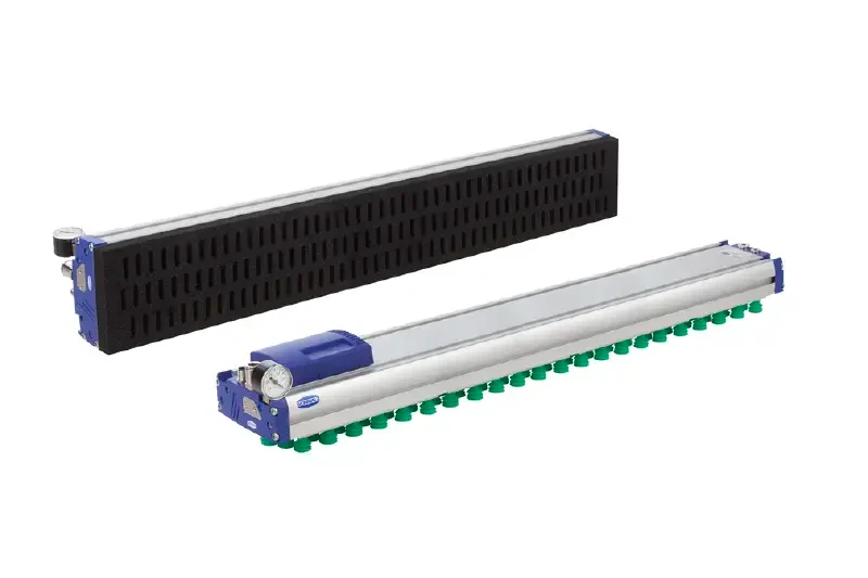
Gripper example of vacuum area for product handlingVacuum gripper · reference imageMechanical, pneumatic or vacuumGrippers and tools

The tool is designed for the product: boxes, bags, trays, bales or parts. Grip form, retention and orientation are evaluated together.

Mechanics
Driven by motor or servo, with opening and force adjusted according to the tool. The handle can dispense compressed air.
Pneumatics
Actuators and valves for grip and release; pressure and air consumption defined for the application.
Vacuum
Suction cups for gripping the surface, with assessment of sealing, porosity, packaging resistance and load retention.
Guidance
The rotation of the gripper guides the product during the cycle and layer formation. Drive and positions are defined in the project.
Reference image · Schmalz
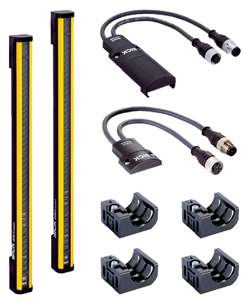
Example of light curtain assembly with emitter, receiver and mounting bracketsLight curtain · reference imageLayout, access and requirements of NR-12Operation protection

Protective measures are defined by risk assessment, considering the layout, supply and frequency of access to the machine.

Grating
Physical barriers and interlocking access, according to the needs of the operation.
Light curtain
Optical detection at planned accesses. Distances, stopping and restarting are defined in the safety analysis.
Laser scanner
Monitoring of areas with zones configured for the chosen layout and security architecture.
Set
Protections, interlocks and stop functions are integrated and validated to meet applicable NR-12 requirements.
Reference image · SICK
Request configuration for your project
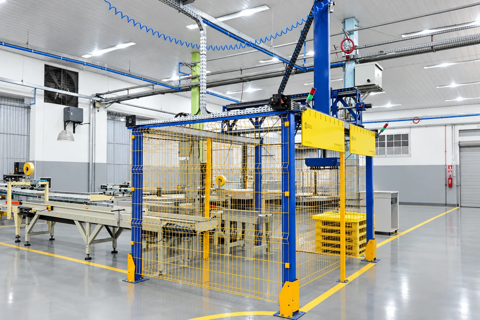
Overview of the Carioli Cartesian robot with conveyors and safety enclosure at Midiograf
Carioli installation at Midiograf. Installation registration provided by Carioli.

In industry · Midiograf

More rhythm. Less manual effort.

In the operation reported by Nivaldo Benvenho, the team went from 5 to 3 people and the line speed went from 240 to up to 300 m/min, in the context of small boxes.

Discover the application and the complete report from those who follow the production.

See the case results

Which model suits your operation?

Share the product, movements and expected cycle. Our engineering evaluates the structure and configuration for your process.

Request an assessment and quote

Enlarged image

Carioli Engenharia will be at Mercopar 2026. Visit booth Z14, October 20-23, from 1 pm to 8 pm, at Centro de Feiras e Eventos Festa da Uva in Caxias do Sul, RS, Brazil.